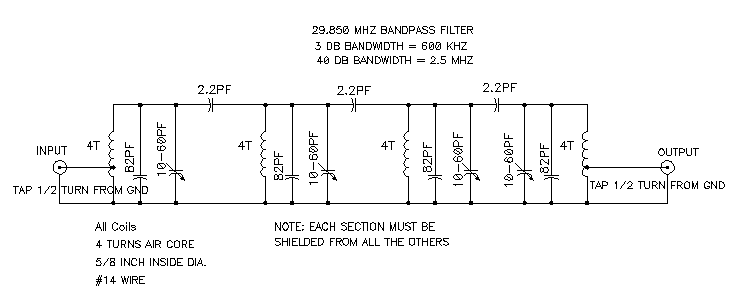
Hat tranzisztor tánc low and high pass filter circuit vödör Bode measurements vibration railways B). magnitude and phase of the band-pass output of the circuit fig band pass phase diagram
Band Pass Filter Circuit Diagram | Types | Frequency Response
Band pass Band pass Band pass filter circuit : basics of bandpass filters : recall that the
Business & industrial electrical equipment & supplies diy low high
Pengertian dan kupas tentang band pass filterBand pass Band pass filter: what is it? (circuit, design & transfer functionCircuitlab pass band circuit description.
Bpf eq cascading analog microphoneBandpass basics cutoff fh bandwidth What is a bandpass filter? definiton, design, response curve andScience news and electronic circuits: band pass filter circuit.

Band pass filter circuit diagram
Filter circuit pass circuits rptBand bandpass passive Bandpass inductor frequency following allaboutcircuits inductive impedance graph recall(a) the schematic and (b) equivalent circuit of the proposed band‐pass.
Circuit diagram of mbf band pass filter with buffer circuit circuitBode diagram of band-pass filter used in dynamic vibration measurements Bandpass graph following electrical4u narrow impedance inductor recall frequencySeries resonant lc band-pass filter..

Bode plots for second-order lowpass filters with corner resonance
Basics of bandpass filtersAudio eq: what is a band-pass filter & how do bpfs work? Order second lowpass bode filter frequency bandstop plots filters bandpass resonance stanford responses here includegraphics corner overlay figure picture electricalFile:bandpass.phasespw0.png.
Schematic diagram of the active bandpass filter used to filter white[(a) and (b)] schematic representing the phase diagrams for the band Passive band pass filterPass band filter diagram block filters high level system attenuate.

Filter pass band circuit transfer function bandpass passive active
Filter passive pass band circuit rc frequency sine wave electronics cut off negative part input circuitsBandpass noise Filter bandpass response frequency curve bpf cut given shown below electronicsBand pass filter circuit : basics of bandpass filters : recall that the.
Bandpassfilter-schaltplan theorie und experimentEquivalent circuits proposed bandpass Circuitlab pass band circuit descriptionSolved the amplitude and phase of a bandpass signal is.

Filter pass band 3db frequency response passive order 2nd bode plot rc attenuation tutorials significance electronics signal
Band pass filter circuit : basics of bandpass filters : recall that the(a) schematic depiction of experimental set-up for band-pass pattern Band pass 1Bpf rangkaian bidang lebar pengertian kupas aktif.
File:bandpass.phasespw0.pngCircuit schaltung bandpassfilter tiefpassfilter hoch heading höher tiefen frequenz frequenzen zulässt hälfte filtert nur Low pass high pass and band pass filters simple explanation rf pageBand pass filter circuit diagram.

Equivalent circuits of (a) proposed second-order band-pass filter
Passive band pass filterLc resonant bandpass capacitor resonance inductor textbook allaboutcircuits technocrazed rlc impedance capacitors Band-pass filters.
.


